I/O Ports
PWM Ports (JR)
Inputs
The VEKTOR Core has 6 PWM input ports, numbered from 1 to 6. These ports can be selectively assigned one of three working modes:
- PWM Input Mode: To capture signals from receivers.
- RPM Input Mode: To capture High-Low levels from Hall sensors and magnets.
- Limit switch input Mode: To capture High-Low levels from Hall sensors and magnets.
As PWM inputs
When set to this operation mode, the PWM input port will receive pulse width modulation with a 20 ms duty cycle, which is typical for RC receiver outputs. In this PWM input mode, the port value will reflect a range between 1000 µs and 2000 µs, corresponding to the physical input received.
As RPM inputs
To get accurate readings, connect our Hall RPM meters to the port with the same polarity as the PWM wires.
When set as RPM meter, the port value will contain the actual RPM count.
The RPM meters can detect rotations from 100 RPM up to 6000 RPM.
As Limit switch input
When this option is selected, the port will output a value of 1000 µs when the button or switch is not pressed and 2000 µs when it is pressed. To use this feature, connect a limit switch to the port that closes the circuit between the ground pin and the signal pin. We have these switches available.
Outputs
The output ports function on a 20 ms duty cycle, with adjustable values ranging from 500 µs to 2500 µs. The configurator allows for the assignment of almost all available functions and controllers to these ports.
JST Ports
Receiver input (USART8)
It is possible to connect a commercial remote control to the VEKTOR Core. We recommend using common serial protocols for this purpose.
The VEKTOR Core supports both PWM ports and serial protocols for remote control with a hardware sender.
These two methods, PWM and serial protocols, are not mutually exclusive and can be used concurrently.
An adapter cable from JST-GH04 to JR is included in the packaging. The power supply for the receiver must be provided separately, such as through a JR patch cable.
Supported protocols
The VEKTOR Core listens on the configured port for incoming control packets. The activation order of sender and receiver is in most cases not import. The system will synchronize itself.
Radio control
The blue LED can be configurad to light up once valid packets are detected.
| Port | Protocol | Sub-protocol | Channels |
| USART8 | FlySky AFHDS-2A | IBUS-PWM | Up to 16 |
| USART8 | FUTABA | S.BUS | Up to 16 |
| USART8 | HoTT | SUMD | Up to 16 |
| USART8 | ELRS | S.BUS, SUMD, (CRSF Q1 25') | Up to 16 |
For short-distance applications (up to 500 meters), we recommend using IBUS receivers, particularly the IA6B receivers paired with Radiomaster transmitters for optimal performance and easy configuration.
For longer-distance applications, we advise using ExpressLRS (ELRS) for a more reliable connection.
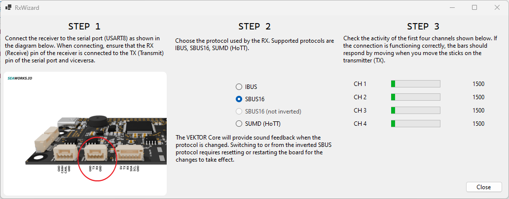
Simple RX wizard
From the main I/O page it is possible to start a simple widget to configure and preview the serial RX channels.
Note that after changing from/to SBUS the controller has to be restarted.
Configurator
Set the desired RX protocol in the USART 8 (X5) tab. Then save the configuration to the flash and reboot/reset the module.
In this tab there is a preview of all 16 (32) available channels.
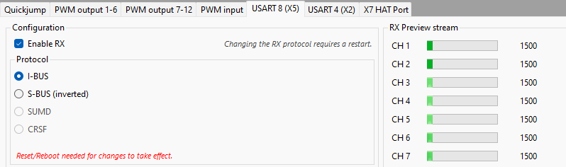
In the right RX preview stream, the serial rx channels should be visible.
USART4
Connect the AHRS module to this port.
GPS port
Supported protocols are NMEA0183 though future firmwares will shift to UBX exclusively. From version 0.93 only the UBX protocol is supported.
The controller will try to autonegotiate UBX parameters.
Should this not work change these manually in U-Center. Connect the UBlox receiver with a serial adapter to the PC.
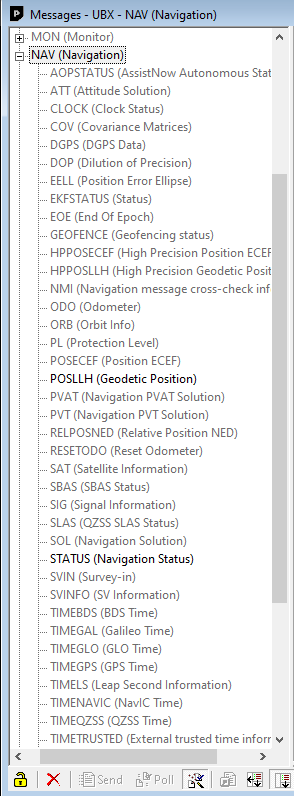
Then open U-Center and connect it to the corresponding COM-Port. Then in (Messages View) change the following parameters:
- CFG -> PRT: Baudrate 115200
- ENABLE NAV-POSLLH
- ENABLE NAV-STATUS
- DISABLE Anything else
- Receiver -> Action -> Save config (ensures the receiver will save changes after restart).
In case the receiver has more than UART port like in case of the F9P (USB, UART1, UART2), make sure to enable these messages for the corresponding UART port.
Both RX and TX lines must be connected to the antenna module. We recommend using at least U-Blox M10Q models with larger sized antennas.
To check whether the controller gets valid UBX packets just select the VALID_GNSS_ACTIVITY for the blue led in settings tab, if UBX packets are detected the led blinks.
![]()
The I2C pins do not need to be connected.