Registers
Overview
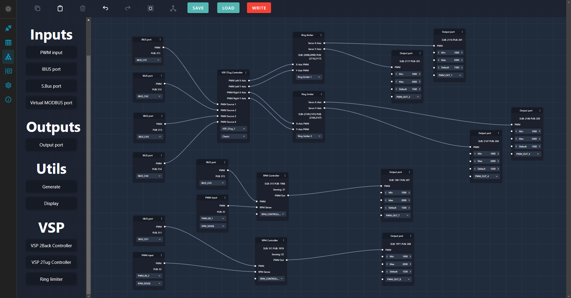
The general control processing follows an input-processing-output architecture. This sequence applies to both control and sensor data, which are handled through logic components. The data path may be as simple as directly wiring the input to an output or as complex as involving tens of logic components between the input and output.
Here is an example of a straightforward configuration demonstrating how to manage two VSP drives using data from the IBus protocol. The data is first processed by a VSP Controller to translate basic controls to the VSP control rod movements. From there, it proceeds to individual ring limiters for each propeller before being directed to the output ports.
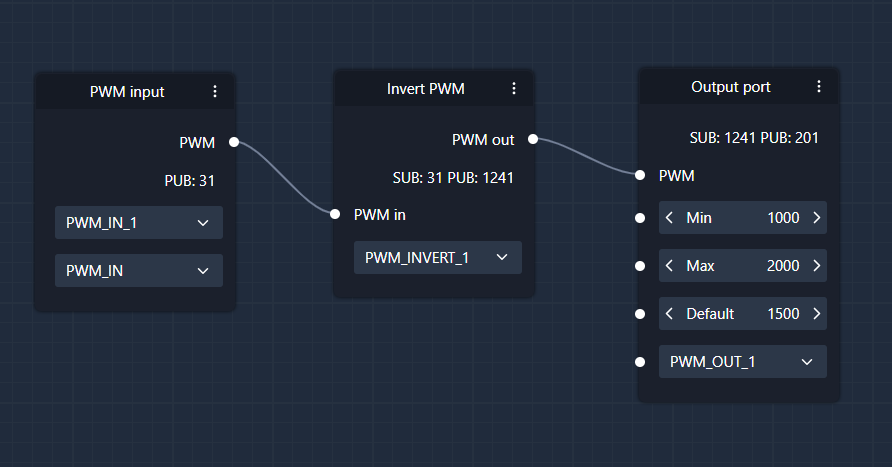
Another basic example, the signal is taken from PWM input 1, inverted, send to PWM output 1:
Register architecture
Registers are virtual memory cells designed to store numeric values. They can be categorized into two functional areas: registers that store information (Generator and Storage Registers) and registers that reference other registers (Processing Registers).
Generator and storage registers
These registers are filled with data in three ways: automatically from ports/sensors, manually by the user, or through outputs of logic nodes.
- Sensor data
- Input data
- Logic node output data
- Parameter/settings data
Processing registers
These registers retrieve and process data from other registers, including generator, parameter, or settings data registers.
- Logic node input data
- Output port data
Example
Consider the inverter node shown previously. The input field labeled 1240 functions as a processing register. In the screenshot, it is configured to read the value from register 335.

When we inspect register 335, assigned to the S.Bus serial data driver, specifically the channel 5, we discover that its current value is 1250 microseconds (PWM signal).

Consequently, the inverter node takes the value from register 335 as its input and generates an output. In this instance, it produces an inverted servo output signal with a value of 1750 microseconds PWM. This resulting value is stored in register 1241, which is categorized as a generator register. This output can now be utilized elsewhere in the system.
Compound registers
32-bit float values are split across two 16-bit registers, into a lower and a higher part. These values have to be rebuilt into floats on the client side (PC companion or single-board computers). The same process applies in the reverse direction. The VEKTOR Core will accept two register values and rebuild the float value internally.
Float values can be found in USV Studio by toggling "Compound registers" switch in the Registers view.