VEKTOR Autopilot (SKU: 1551)
This board is designed to support all the basic functions of the INAV and Ardupilot projects.
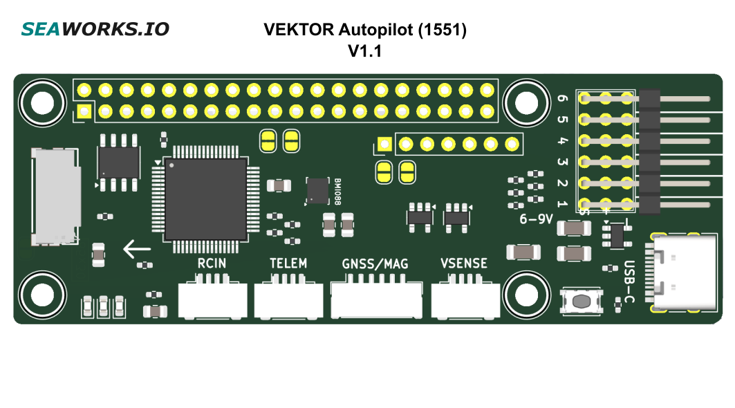
The six PWM output ports allow connection to essential propulsion configurations, such as steering (rudder) and propellers, with or without differential steering.
For the software capabilites please refer to the respective projects:
We do not provide free support for the above-mentioned software or their respective configuration tools.
It can operate in standalone mode with minimal configuration or can supply stabilized SBUS signals to our VEKTOR Core to enable complex propulsion schemes. The two boards are stackable and can be easily interconnected.
Physically it follows the width of the Raspberry Pi Zero and the length of the standard Raspberry Pi. The serial port on the 40pin header is also compatible with the Raspberry Pi pins.
The module is designed to operate without the need for soldering. The JST-GH connectors ensure vibration-resistant connections. However, all six PWM outputs are mirrored on the underside with corresponding solder pads, should the need arise.
The average cold-start time with Ardupilot is around 10 seconds.
Technical specifications
| SKU: | 1551 |
| Supply Voltage (Ub): | 6-9V |
| Power consumption: | Standby current approx. 200 mA |
| PWM outputs: | 6 outputs • PWM (500 - 2500 us) |
| Additional ports: | • UART JST-GH 4pin • UART JST-GH 4pin with RX hardware inverter • GPS/i2c combo port JST-GH 6pin • UART Raspberry Pi compatible header • Power+UART HAT port 7pin • USB-C |
| Buttons: | • Boot button |
| Protection features: | • EMI • ESD up to 15kV (PWM/UART) |
| CPU: | 168MHz ARM M4 (STM32F405) |
| IMU: | BOSCH Sensortec BMI088 |
| Battery sense: | • Analog sense port • Voltage divider up to 6S (22V) |
| Blackbox: | • MicroSD slot |
| Operating temperature range: | 0 – 60° C |
| Maximal relative air humidity: | Max. 85 % |
| Dimensions: | 85.6 mm x 30.0 mm x 1.6mm Raspberry Pi Zero hole layout |
| Regulatory: | RoHS compliant Not suited for anything that flies in any manner! |
The use of this product, parts of it, certain software/hardware combinations, unsupervised use, may not be permitted in your country! Compliance to local laws is solely the responsibility of the user! This product is shipped without firmware; the user must install the firmware themselves and assumes full responsibility for doing so. The warranty and support applies exclusively to the hardware (printed circuit board and components) and does not cover any software-related issues. No responsibility is assumed for the use of this product in any form, including, but not limited to, its use in combination with any software or hardware. No liability is accepted for any damage caused by this product under any circumstances. The correct configuration is the responsibility of the user.
Operating system and Firmware
Vektor Autopilot runs ArduPilot natively, with configurations based on the ArduRover or ArduSub platforms. Most functions are those provided by ArduPilot for these vehicle types, including navigation, control modes, and sensor support.
The operating system is ChibiOS.
More in this section
Requirements
Physical
The Controller must be placed within a dry zone, properly fastened with screws to the vehicle hull.
An Arrow indicates the forward direction of the vehicle, the controller has to be placed accordingly. A misplacement will cause the IMU not to work properly.
We recommend mounting the board with rubber standoffs to minimize vibrations and enable the IMU to provide more accurate data.
Electrical
The Controller works in a range from 6* V to 9 V. The idle current consumption is around 200mA.
A steady current flow is necessary to power up all systems and ensure a reliable operation. Please consider this while designing the electrical part of your USV.
The Controller can be powered via all PWM connectors, 7pin connector or optionally the power module port. The PWM ports and the 7pin port are electrically interconnected.
It is possible to power only the CPU and sensor part through the USB-C port. This feature serves testing and configuration purposes. In production use do not use the USB-C port to power the Controller.
All UART JST-GH ports are provided with stable 5V, combined they shouldn't draw more than 500mA.
*5V BECs are also supported but some older RX and GPS peripherals may not work correctly. Modern peripherals (2020+) should be compatible.
When supplying 5V, the GPS and RX port will output 4V5 (4.5V). 4V5 works with most peripherals, but not all, especially older ones like mentioned.