Common power and signal rails
The VEKTOR Autopilot includes ports that share the same power line or signal. The graphics below illustrate these shared connections for better understanding:
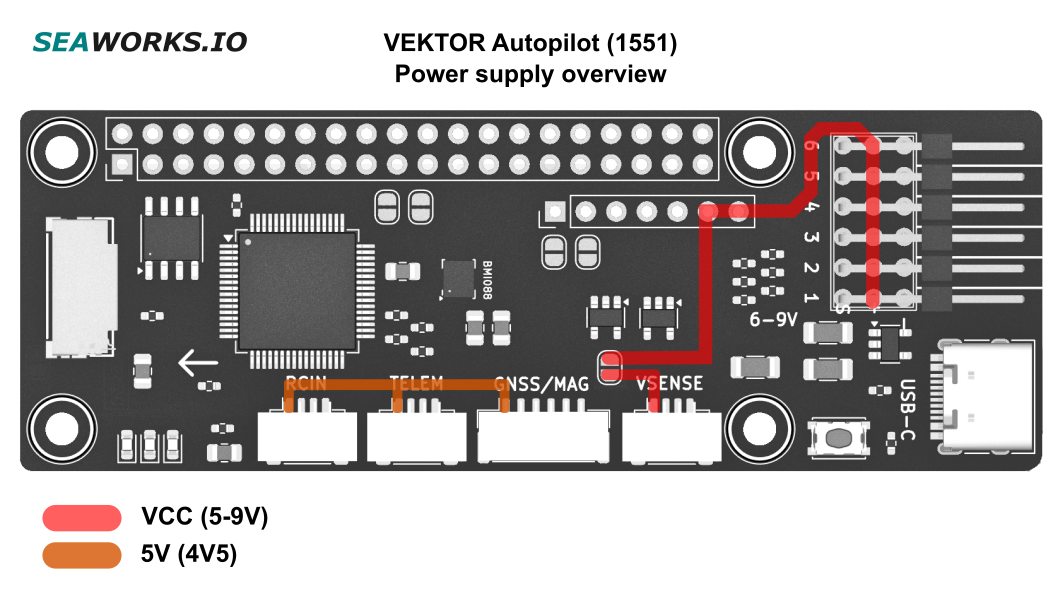
BEC power rail
BEC power (6-9V) is provided through the PWM connectors or the 7pin HAT Connector. These two are interconnected through a wide copper trace.
The BEC pin of the power module port (*ST-GH connector) can be connected to the main power rail via a solder bridge. This decision should be made carefully, as most power modules provide a maximum of 2A, which is often insufficient for high-power servos. Additionally, small JST connectors are not designed for high currents, making them unsuitable for handling peak power demands from modern servos.
However, the option to power the module through the JST-GH connector is retained for cases where no power is supplied via the PWM ports. In such scenarios, 2A is sufficient to power the CPU, receiver (RX), and GPS module.
Warning: Connecting both a power module (with the solder bridge enabled) and an ESC with BEC to the PWM port can cause severe damage to all connected components. This configuration may result in power conflicts, overcurrent, or voltage regulation issues, leading to potential hardware failure and damage.
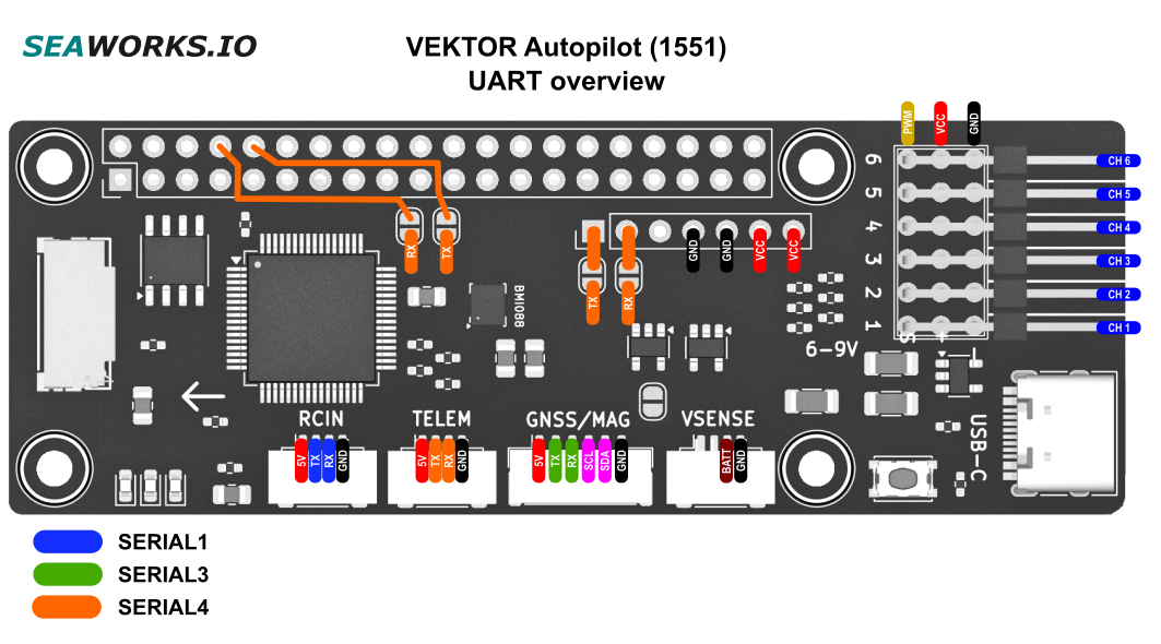
Serial4 (TELEM)
The serial port 4 of the module is connected to the JST-GH port labeled TELEM. This port can also be used for any other application and is fully bidirectional.
Through four solder bridges this signal can be relayed either through the 7pin HAT connector or the 40pin Raspberry Pi interface. Signals can be so sent and received from the Autopilot to the VEKTOR Core through the 7pin connector or a Raspberry Pi.
In the last configuration a Raspberry Pi can be used as a mission computer and connect through MAVLink with the Autopilot.
Only one device can be connected to the Serial4 port at a time, regardless of which connector is used.