VEKTOR Autopilot (for PX4)
SKU: 1551
The use of this product, parts of it, certain software/hardware combinations, unsupervised use, may not be permitted in your country! Compliance to local laws is solely the responsibility of the user! This product is shipped without firmware; the user must install the firmware themselves and assumes full responsibility for doing so. The warranty and support applies exclusively to the hardware (printed circuit board and components) and does not cover any software-related issues.
No responsibility is assumed for the use of this product in any form, including, but not limited to, its use in combination with any software or hardware.
No liability is accepted for any damage caused by this product under any circumstances.
The correct configuration is the responsibility of the user.
With ArduPilot the software Mission planner is needed to configure the board.
When using inav, the iNav Configurator is needed.
Peripherals
GNSS: We recommend using UBlox M10 modules or newer. The GPS module must integrate a compass. Almost all M10 modules on the market have a compass, but some don't.
The default firmware will look for any HMC5883L or QMC5883L compasses connected on the I2C bus during boot. You may need to rotate the compass orientation.
The use of sound modules (loudspeakers) can negatively impact the accuracy of the compass, especially in small spaces.
The precision of the navigation is higlhly dependent on the accuracy of the provided GPS/GNSS data.
M8 / M10 receivers alone provide an accuracy of 1-2m. Their advantage is that they don't require any further accessories and work well anywhere.
To achieve sub-meter accuracy, we recommend using a RTK capable systems and GNSS receivers like the F9P.
More information about configuring RTK here.
A good tuning of all PID parameters is also required.
RX: This module only works with digital serial protocols. Therefore only RX modules with SBUS, IBUS or CRSF (ELRS), SUMD. Consider using ELRS when building a new system.
HoTT telemetry is also activated and supported.
Check the list of supported RX systems for ArduPilot and iNav.
For new builds, we recommend using a 7.2V or 8.4V architecture for the BEC, servos, and other peripherals. A higher voltage architecture provides several advantages, including improved stability, better performance, and a higher current capacity.
Power
The BEC (Battery Eliminator Circuit) inside an ESC can supply regulated voltage to power not only the servos but also the entire autopilot system, including the flight controller, GPS, and receiver. When you connect an ESC with an active BEC to a PWM port on the autopilot, the power lines from that ESC provide the necessary voltage to all connected devices.
However, if you have multiple ESCs with BECs connected to the same system, you must ensure that only one BEC is powering the autopilot. This is because connecting multiple BECs in parallel can create voltage conflicts, which can damage the electronics. On JR-style PWM connectors, this is commonly achieved by not connecting the VCC pin on the extra ESCs, so their BECs do not feed power to the autopilot, leaving only the designated ESC to supply power. In short:
- One BEC → powers autopilot + GPS + RX + servos.
- Multiple ESCs → only one BEC connected; others’ VCC disconnected.
For Voltage sensing: use the proper pin. The voltage is divided internally. The maximum voltage is 26V.
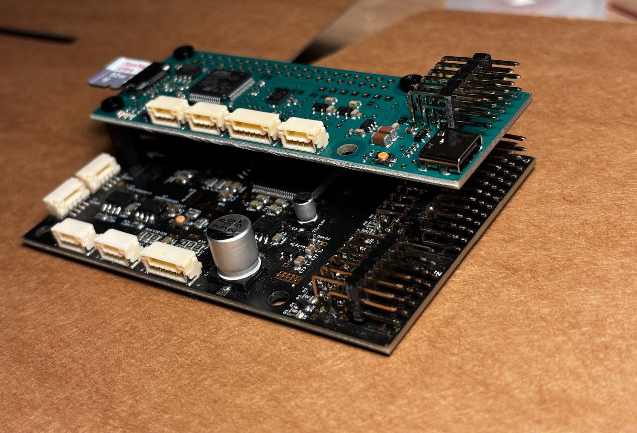
Use with VEKTOR Core
Also see the comparison page VEKTOR Core/Autopilot.
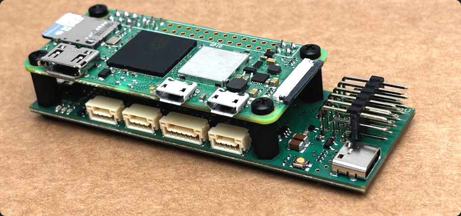
The VEKTOR Autopilot functions as a HAT (Hardware Attached on Top) on the VEKTOR Core, allowing the two modules to interconnect the power pins. The Autopilot can be configured to send MAVLink or SBUS signals through the HAT port to the VEKTOR Core, enabling it to control complex propulsion systems and eliminating the need for a dedicated RX.
This integration enables the direct transmission of autopilot signals, such as AHRS, GPS data and automated throttle and steering, to the VEKTOR Core.
Other specific signals, such as switches, that need to be transmitted to the VEKTOR Core must be configured as passthrough signals in the Autopilot configuration software.
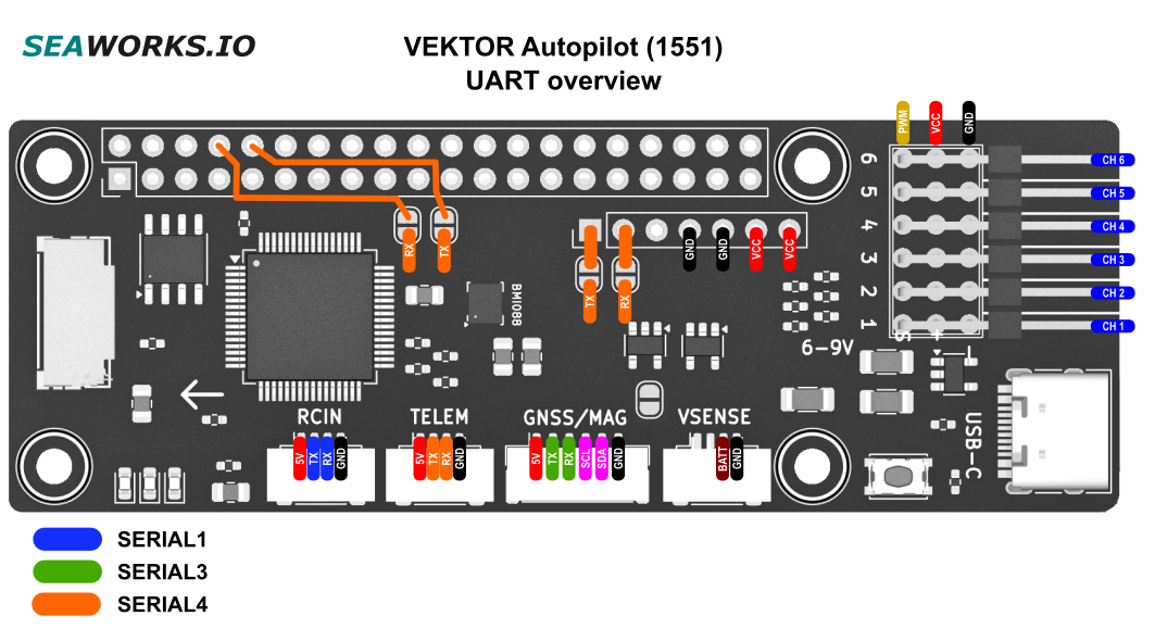
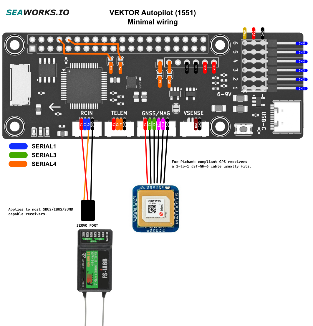
Wiring example
Wire colors may change, RX connects to TX and viceversa.
The Autopilot only supports receivers that output a serial signal like IBUS, SBUS, SUMD, ELRS..
The easiest and most reliable way is to connect an ELRS serial receiver.
For complex wiring also look up the common power and signal rails.
Receivers with many PWM ports and a serial output can be used togheter with the Autopilot. A careful channel mapping on the transmitter is necessary. It is then possible to combine the serial signal to the Autopilot and use the remaining PWM ports on the receiver.
For short distance applications we recommend FlySky iA6B and iA10 receivers, which have PWM outputs and a serial output.
This is also doable with some Graupner HoTT receivers.
- We prioritize the use of electronic components from manufacturers located within the European Union 🇪🇺
- 100% INAV/PX4/ArduPilot compatible architecture
- Waypoint navigation
- Mission planning
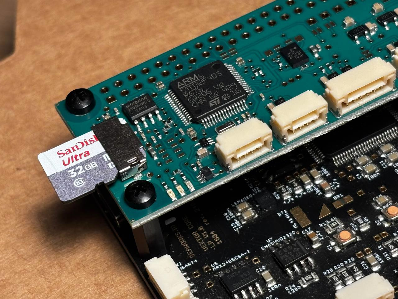
- ARM Cortex-M4 @ 168MHz
- Bosch Sensortec BMI088 High-precision, industrial-grade IMU
- RCIN port for SBUS, IBUS, SUMD, ELRS and other serial protocols
- Supports SBUS with activable RX hardware inverter
- 6x PWM output channels (JR connectors and solder pads)
- DSHOT supported on all channels
- Output groups: (S1,S2),(S2,S3),(S4,S5)
- Telemetry port
- SBUS out and HoTT telemetry enabled by default
- MicroSD slot to store mission data, logs and blackbox data
- Port for voltage sensing
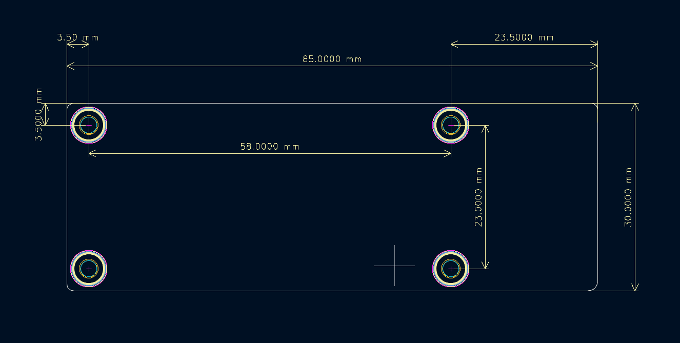
- Raspberry Pi Zero formfactor (85x30mm)
- Compatible with VEKTOR Core, Raspberry Pi or standalone mode
- USB-C programming/configuration interface
- (5*) 6-9V input voltage from PWM pin header
- Can also be powered from USB-C or Power module port (via solder bridge).
- Possible MAVLink interconnect with Nvidia Jetson or Raspberry Pi over 40pin header (activated via solder bridge).
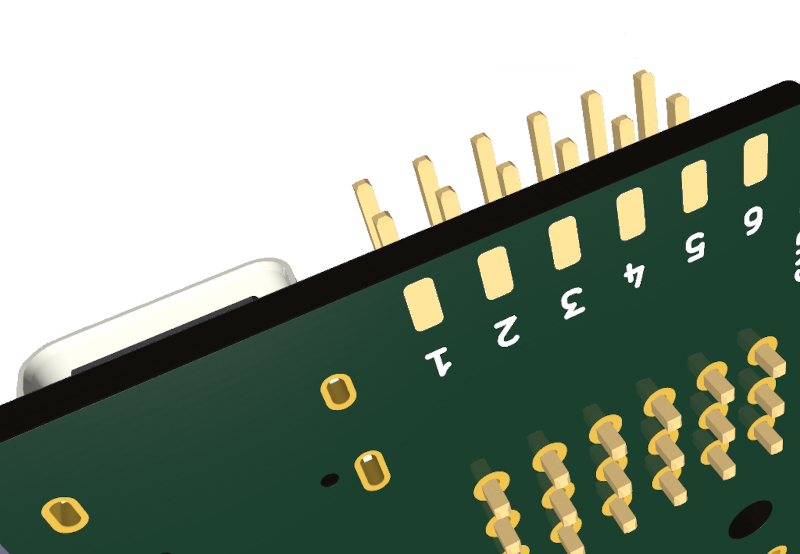
- 7pin connector with high current passthrough and UART port for SBUS input, as HAT on the VEKTOR Core
- Gold-plated contacts
- Samsung Electro-Mechanics Resistors
- Japanese capacitors by Murata
- Vibration resistant JST-GH connectors
- Automotive grade ESD protection up to 15kV
- EMI Filtered ports
- Service lifetime: 500 hours **
- Memory lifetime: 10000 write cycles
* 5V are also supported but some older RX and GPS peripherals may not work correctly. Modern peripherals (2020+) should be compatible.
Suited for:
- USV, UGV, Robots
- Academia, schools, research
Variant with barometer available.
Also available with encrypted datalink. Contact us for further details.
Not suited for anything that flies in any manner!Regulatory compliance has to be obtained by the system integrator/OEM.
This product is RoHS compliant.
** In practice, actual service life can vary considerably depending on operating environment and usage. Especially harsh conditions—such as high humidity, salt exposure, temperature extremes, or mechanical stress—as well as incorrect installation or use outside specified parameters, can significantly reduce the expected lifetime. This also applies the other way around, in a good environment and low write cycles the lifetime can be much longer.
This product is not an independently functional unit and DOES REQUIRE professional installation and configuration.
This product requires a complex configuration process with a prior use case planning, and is not plug-and-play by any means.
This product is sold as PART and not as final product, therefore WEEE and EMC compliance is the responsibility of the system integrator/OEM.
EMC best practices are respected in the design of this product, including:
- Ground planes: Solid, low-impedance ground return paths.
- Decoupling capacitors at every power pin.
- LC filters on supply inputs.
- Short traces with no stubs on high-speed lines.
- Ferrite beads for EMI filtering
- Controlled impedance for SPI.
* The appearance and design of the board are subject to changes. The functionality and size always remain unchanged.
Base price 65€ (excl. DPH/VAT) per unit.
Upon request, we provide a variant of this product with potting (plastic, resin).