Component: VSP controller
The VEKTOR Core is equipped with four virtual VSP (Voith-Schneider Propeller) controllers, each designed to fully electronically control a VSP drive along with its respective motor. This allows even scale vehicles with complex propeller configurations to be easily managed. Properly configuring a VSP is a complex process, requiring the correct adjustment of several parameters to ensure optimal performance.
Propeller settings
Configuration
Unlike conventional azimuth thrusters, VSPs are controlled via a dedicated control rod. The position of this rod determines both the magnitude and direction of the thrust generated by the VSP.
Generally:
- Movements along the X-axis of the control rod produce forward or backward thrust, propelling the vehicle in those directions.
- Movements along the Y-axis generate lateral thrust, enabling the vehicle to move sideways to the left or right.
X and Y axis inputs
It is important to assign control channels appropriately. For example, on a ship equipped with VSPs at the aft:
- The Y-axis should be configured to function as a rudder, controlling lateral movement and direction.
- The X-axis should be assigned to throttle control, managing forward and backward propulsion.

The correct configuration of a VSP is highly dependent on the specific characteristics of the vehicle and the placement of the propeller. As such, there is no universal rule of thumb for setting it up. Proper configuration typically requires a thorough understanding of how the propeller functions and interacts with the vehicle dynamics.
The settings configured in the ring limiter section also play a significant role in influencing the behavior of the VSP. These settings directly affect the angle, range and limits of the control rod's movement, which in turn impacts the thrust magnitude and direction. Proper calibration of the ring limiter is essential to ensure efficient operation of the VSP.
Ring limiter
The ring limiter in a VSP serves several key functions, and its configuration is essential:
Defines Operational Limits: It restricts the movement range of the control rod, ensuring the VSP operates within a safe and optimal angular range.
Prevents Damage: By limiting over-travel, it protects the propeller and servos from excessive stress and potential mechanical failure.
Improves Stability: It ensures the thrust vector remains within controlled angles.
Limiter radius
Considering that the center of idle servos is typically around 1500 µs, the VSP control rod servos should also idle at this value. The limiter radius defines the maximum travel range of the servos, ensuring they stay within a safe operational limit. For example, a limiter radius of 50 µs would result in a servo range of 1400 to 1600 µs.
The ideal travel radius is usually provided by the manufacturer and should be as large as possible without causing the control rod to contact the propeller.
X and Y axis center
The control rod should stay centered within the VSP. If it's not, perform a calibration to re-center it. Proper calibration ensures the VSP operates as intended.
Thrust angle correction
This option shifts the control rod angle relative to the input controls, corresponding to movements along the X and Y axes. The thrust direction is determined by the blade pitch, which is controlled by the rod geometry and synchronized with the hub's rotation.
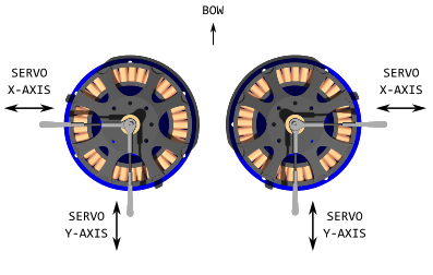
E.g. When two VSPs are placed side by side and rotate in opposite directions, their rods must be adjusted to maintain the same thrust angle. Specifically, the rods need to be offset by 180 degrees to account for the opposing rotational directions. This 180-degree shift ensures that the blades on both VSPs adjust their pitch at the correct phase of rotation, aligning the thrust vectors to produce force in the same direction.
RPM controller
The VEKTOR Core also features a constant RPM function, which ensures stable motor speed and consistent thrust output.
During the movement of the control rod, the RPM can change drastically and needs to be continuously corrected to ensure stable thrust production and precise control of the VSP. This constant correction maintains consistent performance and prevents fluctuations that could affect the maneuverability.
Sensor input
Select the PWM input pin of the VECTOR Core that is designated to capture the RPM signal. Ensure that the input is also configured as "RPM input" in the Inputs configuration tab.
Start switch
Set the PWM source or TX switch that will control the enable/disable function for the motor and the RPM controller. The signal is interpreted as follows:
- Below 1200 µs: Motor off
- Above 1800 µs: Motor running
- Between 1200 µs and 1800 µs: The current state is maintained
Target RPM
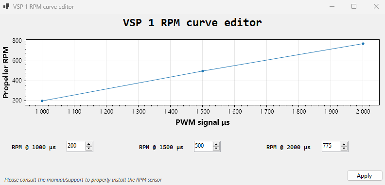
Set the desired RPM value for the VSP. This value is specific to each vehicle or configuration. A safe range is typically between 200 and 800 RPM.
Variable speed
When enabled, the option to create an RPM curve becomes available. It is also necessary to configure a potentiometer or knob. This curve will define values based on an RPM-to-PWM relationship.

Spin-up PWM
This parameter sets the initial PWM value used when the engine starts and serves as a baseline for the RPM controller. Brushless motors often face difficulties with low-range PWM values during spin-up. It is recommended to begin testing with values around 1500 µs and gradually reduce them if necessary.
Example configuration
Minimal VSP tug
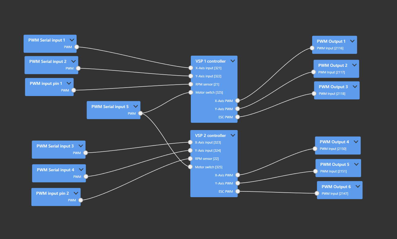
With RPM sensors, the logic schema will look like this: both self-centering sticks on the TX are mapped directly to the VSP control rods of the respective propellers. A switch button is used to activate or deactivate the VSP engines and set them to the desired RPM value. The PWM input pins 1 and 2 of the VEKTOR Core are configured as "RPM input" and are used to transmit this signal to the VSP controllers.

In the VSP controller settings, the angle correction must be configured based on the placement each VSP and its direction of rotation.