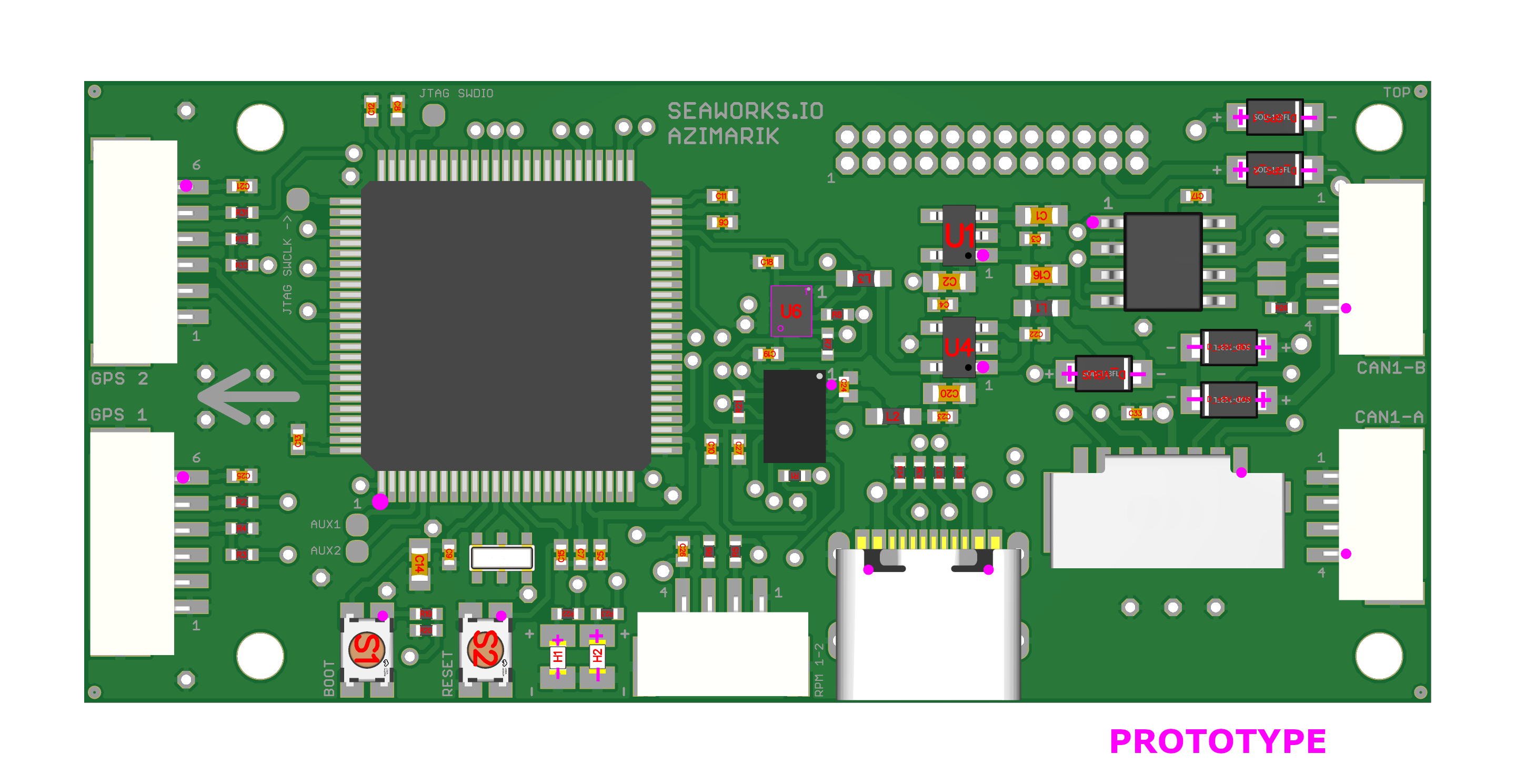
AZIMARIK Autopilot (SKU: 1590)
This system is designed to support all the advanced functions of the Ardupilot and PX4 projects. Azimarik is designed for UAVs and USVs undertaking long survey missions where endurance is critical.
It is built around CAN communication as its core feature. This means it relies primarily on Controller Area Network (CAN) to connect and communicate with other devices and sensors. Using CAN allows for reliable and efficient data exchange, even in complex networks. It also simplifies the vehicle’s wiring and makes debugging easier.
The following datasheet applies universally to all versions. However, different variations in quality and grades are available, which may affect the intended usage.
AZIMARIK Autopilot consists of two stacked boards: the Autopilot board and the Hub board.
The Autopilot board can function independently as a central processor connected and powered solely via CAN for the vehicle.
For a more conventional setup, the Hub board adds four general-purpose UART ports and includes a 5A BEC to power connected peripherals. Additionally, it provides two extra CAN ports with a dedicated controller to support CAN redundancy if needed.
When running PX4, two AZIMARIK Autopilots can be integrated into a vehicle to create a redundant network.
For the software capabilites please refer to the respective projects:
We do not provide free support for the above-mentioned software or their respective configuration tools.
The module is designed to operate without the need for soldering. The JST-GH connectors ensure vibration-resistant connections.
The average cold-start time with Ardupilot is around 10 seconds.
Technical specifications
| SKU: | 1590 |
| Supply Voltage (Ub): | BATTERY SENSE: 5-28V CAN 1: 5V |
| Power consumption: | Standby current approx. 200 mA |
| PWM outputs: | 8 JR 2.54mm pitch outputs • PWM (500 - 2500 us) |
| Ports (AZIMARIK): | • GPS/I2C combo port 1 JST-GH 6pin • GPS/I2C combo port 2 JST-GH 6pin • CAN 1-A JST-GH 4pin • CAN 1-B JST-GH 4pin • RPM Sense JST-GH 4pin • USB-C • MicroSD • SWD debug pads |
| Ports (AZIMARIK-HUB): | • UART JST-GH 4pin • UART JST-GH 4pin • UART JST-GH 4pin • UART JST-GH 4pin • CAN 2-A JST-GH 4pin • CAN 2-B JST-GH 4pin • XT30 |
| Buttons: | • Boot button • Reset button |
| Protection features: | • EMI • ESD up to 15kV |
| MCU: | 480MHz Arm® Cortex®-M7 (STM32H743) |
| IMU: | BOSCH Sensortec BMI088 |
| Barometer: | Infineon DPS310 |
| BEC (AZIMARIK-HUB): | 5.6V @ 5A for UART peripherals and CAN 2 |
| Extensions: | • MicroSD slot • 120 Ω CAN terminators activated by solder bridges. |
| Operating temperature range: | 0 – 60° C |
| Maximal relative air humidity: | Max. 85 % |
| Dimensions: | 65.6 mm x 30.0 mm |
| Regulatory: | RoHS compliant |
| Other: | H7 MCU supports optional bit inversion on all UARTs. |
Operating system and Firmware
AZIMARIK Autopilot runs ArduPilot natively, with configurations based on the ArduCopter, ArduPlane, ArduRover or ArduSub platforms. Most functions are those provided by ArduPilot for these vehicle types, including navigation, control modes, and sensor support.
The operating system is ChibiOS.
Requirements
Physical
The Controller must be placed within a dry zone, properly fastened with screws to the vehicle hull while ensuring good grounding to other systems.
An Arrow indicates the forward direction of the vehicle, the controller has to be placed accordingly. A misplacement will cause the IMU not to work properly.
In order to work properly, the controller should be placed as close as possible to the center of gravity of the vehicle.
We recommend mounting the board with rubber standoffs to minimize vibrations and enable the IMU to provide more accurate data.
Electrical
The BEC in the AZIMARIK-HUB and power supply for the controller works in a range from 5 V to 60 V when supplied by the XT30 connector. The idle current consumption is around 200mA.
When powered by the CAN 1 port, a voltage of 5V +- 0.5V has to be supplied.
A steady current flow is necessary to power up all systems and ensure a reliable operation. Please consider this while designing the electrical part of your USV/UAV.
It is possible to power only the MCU and sensor part through the USB-C port. This feature serves testing and configuration purposes. In production use do not use the USB-C port to power the Controller.
All UART JST-GH ports are provided with stable 5V, they shouldn't draw more than 500mA each.
When supplying 5V, the GPS and RX port will output 4V5 (4.5V). 4V5 works with most peripherals, but not all, especially older ones.