Hardware & Pinouts
Hardware
Power rails
The module can be powered through any of the following three sources at the same time:
- CAN bus power rail
- VCC power from the servo connector
- USB-C port
To provide power to the GPS and RCIN ports, the VCC power rail must be connected to an external supply, such as an ESC or BEC.
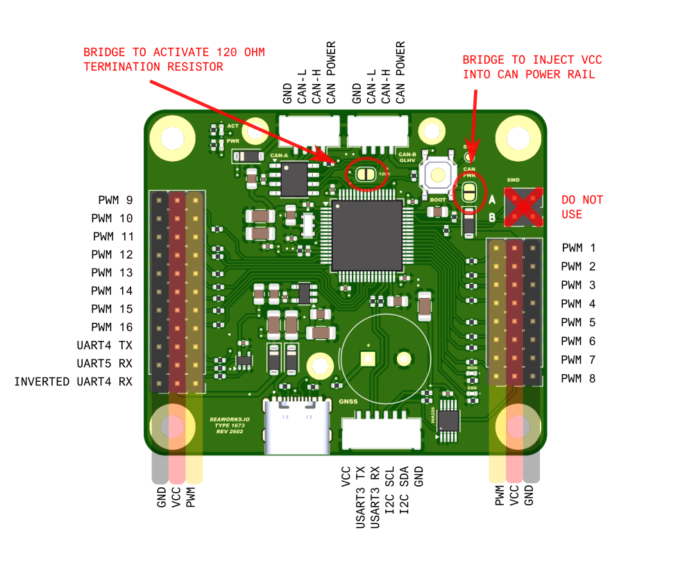
Power may be routed from the VCC rail to the CAN bus power rail by shorting the solder-bridge. Reverse power flow from the CAN rail to the VCC rail is blocked.
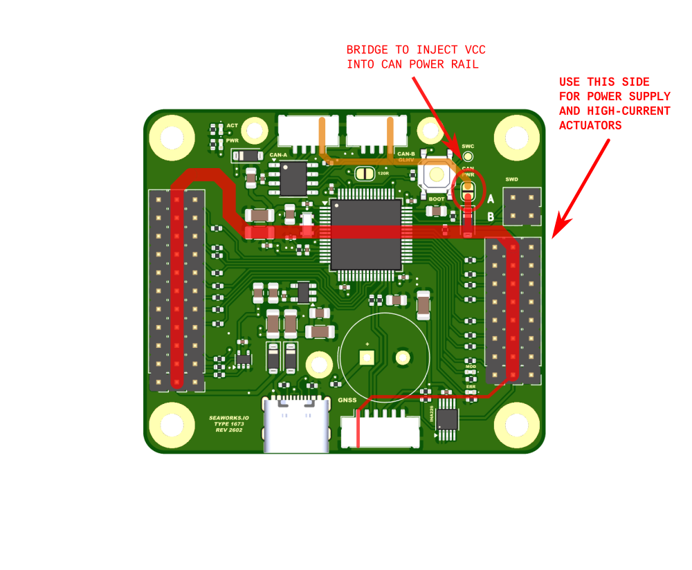
The VCC power source, such as an ESC or BEC, must be connected on the right-hand side of the board. High-current loads, including VSP servos, must also be connected on this side. The corresponding PCB traces are dimensioned for currents of several amperes.
The auxiliary connectors on the left-hand side are intended for lower-power devices, such as small servos, switches, or receivers. The total continuous current drawn from these connectors must not exceed 2 A.
When driving two Voith-Schneider propellers we recommend to connect at least a 5A or more power source, ideally 6V or more.
A steady current flow is necessary to power up all systems and ensure a reliable operation. Please consider this while designing the electrical part of your vehicle. It is strongly advised, if not essential, to position PowerPacks close to any components that have any current draw (such as Voith-Schneider propeller servos).
For new builds, we recommend using a 7.2V or 8.4V architecture for the BEC, servos, and other peripherals. A higher voltage architecture provides several advantages, including improved stability, better performance, and a higher current capacity.
Warning: Connecting more than one power source (ESC with/or BEC) can cause severe damage to all connected components. This configuration may result in power conflicts, overcurrent, or voltage regulation issues, leading to potential hardware failure and damage.
That said, if you have multiple ESCs with BECs connected to the same system, you must ensure that only one BEC is powering the module. This is because connecting multiple BECs in parallel can create voltage conflicts, which can damage the electronics. On JR-style PWM connectors, this is commonly achieved by not connecting the VCC pin on the extra ESCs, so their BECs do not feed power to the autopilot, leaving only the designated ESC to supply power. In short:
- One BEC → powers the module via VCC + GPS + RCIN + servos.
- Multiple ESCs → only one BEC connected; others’ VCC disconnected.
When routing VCC power to the CAN bus power rail, ensure a substantial power reserve. Any voltage drop on the CAN power line can compromise the operation of other devices on the bus, including the autopilot, potentially leading to critical failures. Overall, this approach is not recommended for safety-critical systems, where the CAN bus should have it's own isolated power source.
USB
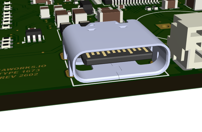
The USB-C compliant port serves exclusively to flash/upgrade the firmware. It also powers up the MCU and CAN part for debug purposes. It is fully reversible and auto-negotiates 5V power.
CAN
A high-speed CAN transceiver is integrated on the module and supports data rates up to 1 Mbps. For bus lengths up to 10 m, operation at the maximum data rate is recommended.
The module includes a solder bridge connected to a 120 Ω termination resistor. Close this bridge only if the module is installed at one end of the CAN bus segment.
CAN is a differential bus system designed to operate with a characteristic line impedance of approximately 120 Ω. To maintain signal integrity, the bus must be terminated with a 120 Ω resistor at each physical end of the cable.
Exactly two termination resistors must be present in a standard linear CAN bus, one at each end of the bus. No additional termination should be added at intermediate nodes.
Without proper termination at both ends of the bus, the network wil not work.
Both CAN bus JST-GH connectors are internally mirrored. The signal lines (CAN-H, CAN-L) as well as the power rails are directly connected in parallel, to serve as a direct bus passthrough
If the 120 Ω termination resistor is enabled, only one JST-GH connector should be used. The module must then be positioned at the end of the CAN bus, with the second connector left unconnected.
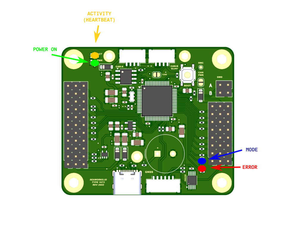
LEDs
This module features four status LEDs:
- GREEN: Indicates a stable power supply is present, provided via CAN, VCC, or USB.
- YELLOW: Firmware heartbeat indicator, typically blinking at 1 Hz.
- BLUE: Mode indicator, controllable from the autopilot.
- RED: Error indicator; connect to the autopilot to read the associated error message.
Pinouts
VSP driver
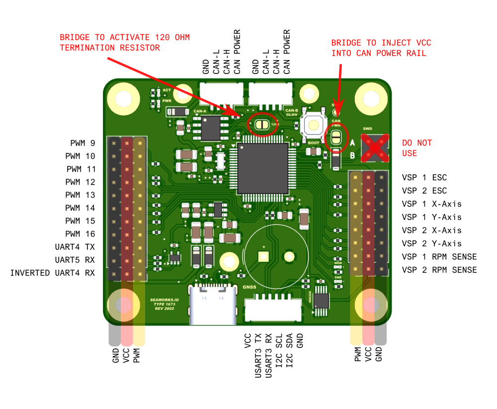
The RCIN signal can be picked up either through UART5 RX or INVERTED UART4 RX, so only one should be connected at a time. For non-inverted signals (e.g. iBUS, HoTT), use the standard UART5 RX port; for SBUS (inverted), use the SBUS UART4 RX port.
AP_Periph
With the standard AP_Periph firmware this module offers 16 fully functional and customizable PWM output channels.
PWM outputs 1 to 6 support DSHOT600 and BDSHOT.